215.631.7111

S-BOND BLOG

Joining Thermal Management Graphite Composites

S-Bond® active solders enable graphite bonding and the joining of other carbon based materials to each other and to most metals within the constraints of thermal expansion mismatch. S-Bond® alloys have active elements such as titanium and cerium added to Sn-Ag, Sn-In-Ag, and Sn-Bi alloys to create a solder that can be reacted directly with the carbon surfaces prior to bonding using specialized S-Bond® treatments for solder joining. Reliable joints have been made between graphite and carbon based materials with all metals including steel, stainless steels, titanium, nickel alloys, copper and aluminum alloys.

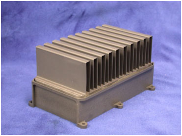
In high power density electronics, there is a need to rapidly spread and dissipate heat generated by the high frequency operations in the electronics.  In order to improve the heat dissipation capacity of graphite based materials, Applied Nanotech developed a new passive thermal management material, CarbAl™, which is a carbon-based material with a unique combination of low density, high thermal diffusivity, and low coefficient of thermal expansion based on Figure 1.

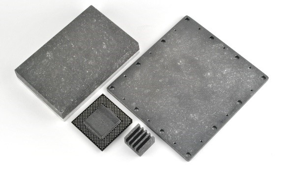
Figure 1. Picture of the CarbAl-G high thermal diffusivity graphite composite.

Applied Nanotech reports that CarbAl™ has a density of 1.75 g/cmcompared to 2.7 g/cmfor aluminum and 8.9 g/cmfor copper. While copper has a slightly higher thermal conductivity than CarbAl™, 390 W/mK compared to 350 W/mK, CarbAl’s thermal diffusivity is approximately 2.9 cm2/sec compared to 0.84 cm2/sec for aluminum and 1.12 cm2/sec for copper.

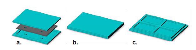
S-Bond Technologies and Applied Nanotech have collaborated to make heat spreaders with CarbAl-G cores combined with copper and aluminum claddings to make the heat spreaders that are more robust and able to be fabricated to support a high density of high power electronic devices, yet be mounted in standard “PC” card configurations as seen in Figure 2.

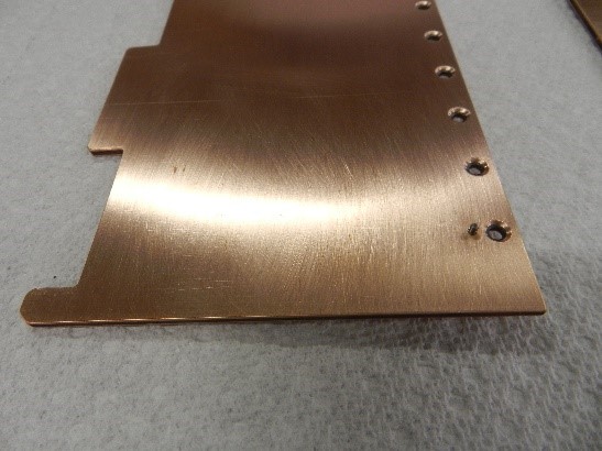
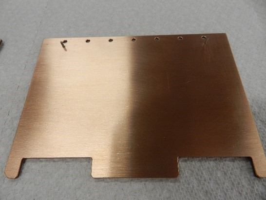
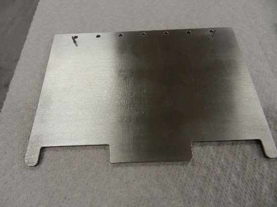
Figure 2. Copper and Aluminum clad CarbAl-G circuit boards.

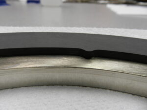
These clad CarbAl-G cored boards have utilized active S-Bond® solder layers to intimately bond and thermally connect the thin copper or aluminum claddings to the lightweight, high thermal diffusivity CarbAl-G composite sheets.

S-Bond® CarbAl-G bonding and joining was thermally activated using S-Bond Technologies proprietary process, which prepared the CarbAl-G surfaces and developed a chemical bond to the surface, through reactions of the active elements in S-Bond® alloy to the graphite in CarbAl-G. These joints start with processing the graphite/carbon surfaces at elevated temperatures in a protective atmosphere furnace with S-Bond® alloy placed on the graphite-carbon surfaces to be joined. At these elevated temperatures, the active elements in S-Bond® (Ti, Ce, etc.) react with the ceramic to develop a chemical bond. After the CarbAl-G is prepared / S-Bond® metallized, the CarbAl-G is then S-Bond® soldered to the aluminum or copper sheets to for a metal clad CarbAl-G composite plate that can then be machined into a heat sink plate to which high power electronic devices be mounted.

The S-Bond® solder joints produced:

  • Are ductile, based on Sn-Ag or Sn-In alloys
  • Exceed the strength of the CarbAl-G
  • Are thermally conductive, with S-Bond® alloys having k = 50 W/(m-K)
  • Are metallic and this electrically conductive with a metallurgical bond

S-Bond Technologies has developed extensive experience in active, S-Bond® solder joining of graphite, carbon and carbide to metals. Contact Us to evaluate our joining solutions for your graphite joining applications. For more information on CarbAl-G, please contact Applied Nanotech. Inc

Bonding Graphite –Ceramic – Stainless Steel Composite Component For Los Alamos National Laboratories

Fabricating Parts for Proton Collimator With S-Bond® Active Solders®
The unique capability of S-Bond solders to join graphite and ceramic to metals was the solution for Los Alamos for fabricating core elements of their Proton Collimator used in its Proton Radiography facility. Conventional brazing was considered but their large differences in Coefficient of Thermal Expansions (CTE’s) limited brazing since on cooling from brazing temperatures (over 800°C), the resultant CTE derived residual stresses would have likely cracked the ceramic, graphite or torn the bond interface. Figure 1 illustrates the graphite – ceramic-stainless steel composite assembly that required stable, thermally and electrical conductive connection between the assembly’s elements.

Los Alamos researchers reached out to S-Bond Technologies to use its S-Bond solders to join these disparate materials. Normally plating would have to be used to make the ceramic and graphite materials solderable. In the case of S-Bond joining, the same solder and soldering process was used to make the joint between the graphite base, the insulating alumina sheet and the stainless steel plate, as depicted in Figure 1.

Figure1AProtonColimator

Figure 1. Illustration of the proton collimator elements joined with S-Bond solders.

The soldering of this composite started the S-Bond metallization of the bonding surfaces of the graphite base and the alumina insulator. In this process, S-Bond metallization paste was applied to the one surface of the graphite and the two opposite sides of the alumina paste. The graphite and the alumina sheet with pastes applied, were heated to 960C in a vacuum furnace in order to react the elements in the paste with the graphite and ceramic surfaces to create a chemical bond between the solder and the graphite and alumina.  After metallization these parts’ surfaces are solderable with a well bonded interface. The Graphite base, the alumina insulator plate and the stainless steel header were heated to 250C where S-Bond 220 solder filler metal was applied via melting on and mechanical activation (spreading by heated blade or bush) to pre-tin the faying surfaces of the assembly. Once the S-Bond solder filler metal was pre-placed (pre-tinned) the parts kept hot at 250C, were placed together in an alignment fixture to align the constituent parts accurately and then pressed / loaded with 50 lbs of deadweight as the bonded assembly was cooled.

Figures 2 illustrates the solder bonded composite proton beam collimator component. The pictures show the two S-Bond solder interfaces connecting the water cooled Stainless steel end plate, to the ceramic insulator plate, then connected to the graphite cathode.

Figure2aProtonColimatorFigure 2a. Back of S-Bond joined collimator part. Stainless Steel/ceramic insulator/graphite base (from Top to Bottom)

Figure2bProtonColimatorFigure 2b. Side view of S-Bond joined collimator part.

Figure 3 illustrates the Proton Collimator with the S-Bond joined parts being assembled at Los Alamos National Laboratory (LANL). There were two S-Bond joined parts per assembly. These bonded component assemblies worked very well and enables LANL engineers to successfully implement their design.

Figure3ProtonColimator

Figure 3. Proton Collimator with two S-Bond joined composite being mounted.

LANL engineers were able to utilize S-Bond’s unique capability to solder join stainless steel to ceramic to graphite. If you have such joining challenges, Contact Us for incorporating S-Bond joining in your assemblies.


Fabrication of TPG* Thermal Management Parts

LED Headlamp Cooling Enabled by Thermal Pyrolytic Graphite (TPG*) Materials via S-Bond Joining

By          Dr. Ronald Smith, S-Bond Technologies
Dr. Wei Fan, Momentive Performance Materials Inc.

Automotive LED headlights present a thermal management challenge where conventional aluminum- and copper-based heat sinks limit the maximal power loading to LEDs. Thermal Pyrolytic Graphite (TPG*) materials are now being designed into high power LED headlight assemblies to help thermally manage LED (light emitting diode) heat. TPG* materials contain millions of highly-oriented stacked graphene planes forming excellent in-plane thermal conductivity (>1500 W/m-K) with very low density (2.25 g/cm3). TPG-metal composites can simultaneously achieve high thermal conductivity from the TPG core and high mechanical strength from the metal shell.

In testing conducted by Momentive Performance Materials Inc. (“Momentive”) on prototype headlights, data suggests that replacing aluminum fins with metallized TPG plates can reduce total system thermal resistance by 27%, and by inserting a TPG core underneath LED dies, an additional 24% reduction in thermal resistance can be achieved. Furthermore, testing of this integrated headlight assembly demonstrated that TPG material-assisted heat dissipation at these two strategic locations can allow for a twofold increase in power load to the LED.

Various new bonding processes, including diffusion bonding, epoxy bonding, S-Bond soldering and brazing, have been developed to integrate TPG material into metal-encased TPG-metal composites, such as aluminum, copper, tungsten copper, molybdenum copper and ceramics made through encapsulation processes. TPG-metal composites typically behave like solid metal and can be further machined, plated or bonded to other components to meet various requirements.

TPG-metal composites have been incorporated into Momentive’s TC1050* heat spreaders, TMP-EX heat sinks and TMP-FX thermal straps where they can quickly conduct heat away from the heat-generating sources; therefore, greatly increasing LED cooling efficiency and life. A baseline LED conventional headlight assembly (see Figure 1) shows the LED die bonded to a heat spreader and thermally connected to a cooling fin and active fan system. Thermal analysis of this baseline LED headlight indicated that integrating high-thermal conductivity TPG material into the aluminum heat sink base and aluminum heat sink fins could make the greatest impact in increasing heat dissipation of the LED headlight.

HeadLamp1Figure 1.  The baseline LED headlight (VLEDS 9006) illustrating key components for  thermal management.

Next, TPG materials were integrated into various parts of a LED headlight assembly. In this study, three proposed designs were validated in simulation, built and then tested, as shown in Figure 2.

In Design 1, the fin heat exchanger from the baseline assembly was replaced with straight aluminum fins with similar heat dissipation performance.

HeadLamp2


Figure 2.  New designs with TPG material integrated at heat sink fins and heat sink base to improve heat dissipation. Image: Momentive


In Design 2, the aluminum fins were replaced with Momentive’s TMP-FX thermal straps metallized with S-Bond solder. The high-thermal conductivity TPG material spread the heat more uniformly across the entire fin structure; thus, utilizing the fin surface more efficiently. The thin S-Bond coating not only protected the TPG material from moisture and abrasion, but also enabled soldering of TPG material directly to the aluminum base to minimize any interface heat resistance.  Temperature mapping through measurement, as shown in Figure 3, revealed that a thermal resistance of 4.7 oC/W, which was 27% less than the measured resistance of Design 1, was achieved.

HeadLamp3Graph

Figure 3. Measured LED junction temperature (subtracted by ambient temperature)
as a function of input power per LED for the three headlight designs. Note: Test data. Actual results may vary.

In order to facilitate the heat flow from the LED die to the heat sink fins through the narrow neck area, a T-shape TPG tile with 2 mm thickness, as illustrated in Figure 2 as Design 3, was embedded into the aluminum base. This TPG tile, which presented a thermal conductivity 8 times higher than that of aluminum, was first metallized and then brazed into an aluminum enclosure with a T-shape cavity at nearly 600 oC. High temperature braze joints between the TPG material and aluminum and between the aluminum enclosure components provided excellent thermal interfaces and high bonding strength. More importantly, the braze bond endured the downstream S-Bond soldering temperature when the LED dies and TPG fins were attached. This TPG-embedded aluminum heat sink base is a TC1050 heat spreader that can be made via brazing or diffusion bonding processes. With the heat dissipation assist from the TPG tile in the heat sink base, in combination with the S-Bond-joined heat sink fins, the measured thermal resistance of Design 3 was 3.0 oC/W, another 24% reduction as compared to Design 2 (see Figure 3).

Thermal simulation conducted on Designs 1, 2 and 3 with input power of 15 W per LED (30 W total) is illustrated in Figure 4. The simulation results showed that the TPG S-Bond soldered fins in Design 2 reduced the temperature gradient along the fins; hence, increasing the effective area dissipating heat to the air circulation. In the case of Design 3, the T-shape TPG tile in the heat sink base further decreased the temperature gradient between the LED die to the heat sink fins. Compared with Design 1, the combination of the TPG heat sink fins and TPG heat sink base in Design 3 allowed a significantly lower LED temperature.

HeadLamp4thermalimage


Figure 4. Simulated temperature profiles of LED headlights with Design 1, 2 and 3, respectively. Image: Momentive

These studies, conducted by Momentive on its TPG materials and components, have shown that S-Bond metallization and soldering presents a key element to the manufacture of LED headlamps with improved cooling.

If you want to learn more about joining TPG materials, or to otherwise fabricate thermal management components, please Contact Us at S-Bond Technologies or Contact Momentive for data and information on their TPG materials and/or devices.

*TPG and TC1050 are trademarks of Momentive Performance Materials Inc.


Rotating Graphite:Metal Seals

2014-06-20 036
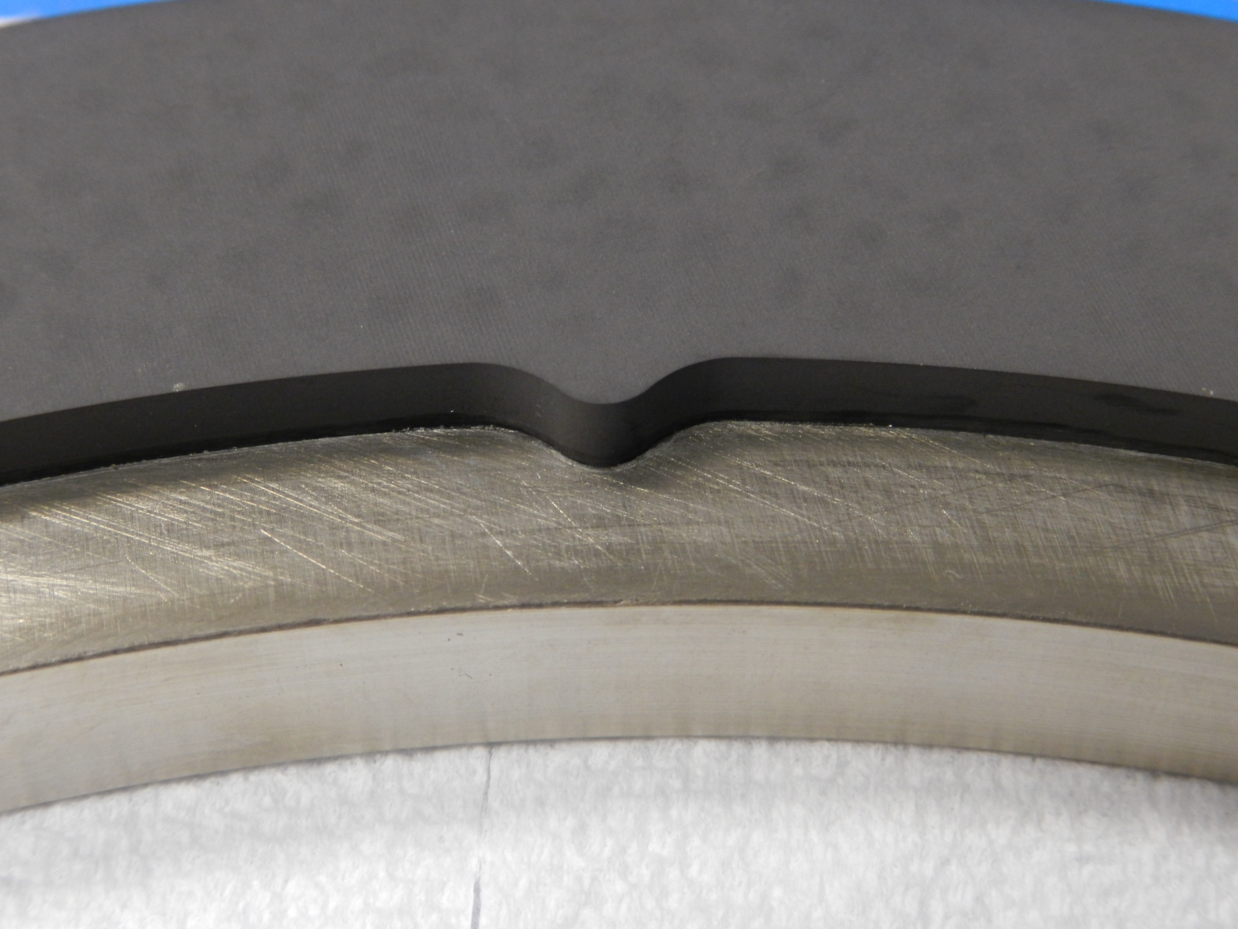
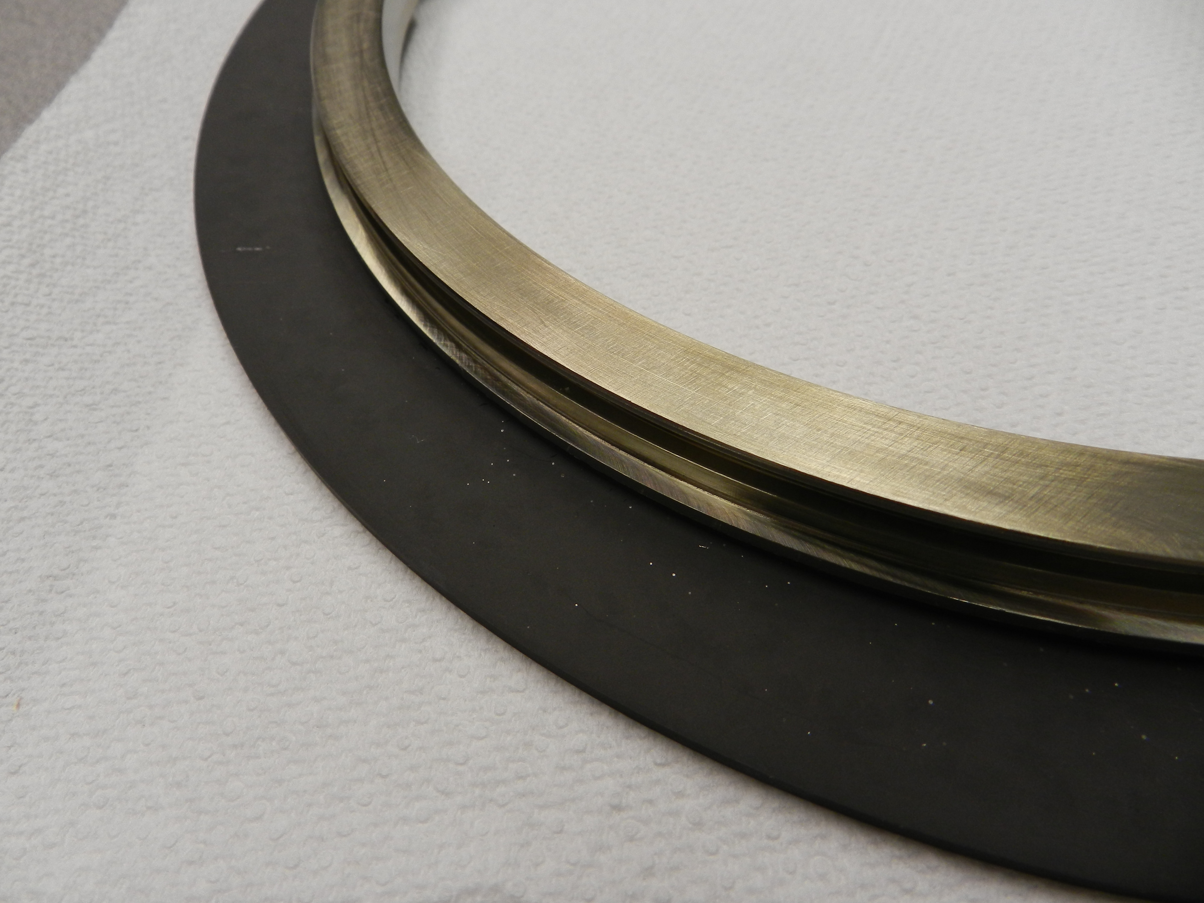
Carbon/graphite compressor seal rings are employed in many compressors and more and more metal backed graphite seals are being used in higher efficiency compressors. Frictional heating of seals can degrade metal backed graphite seals, therefore good thermal contact between the graphite seal ring and the metal backing is needed to improve cooling of the seal. S-Bond Technologies has developed active soldering methods for graphite bonding which is now being used to manufacture rotating metal backed graphite seals.

In the process, graphite rings are initially S-Bond metallized to create a chemically bonded solder to graphite interface. The sequence of bonding is shown in the figures below. After metallization the metal rings’ bonding surface are pre-tinned with S-Bond filler metals, via heating, melting of the solder surfaces on the metal followed by mechanical activation (ultrasonic solder tip agitation). The metallized graphite ring surface, at 250C is pressed against the pre-tinned metal backing ring surface and then the assembled ring is cooled to solidify the solder joint.

These S-Bond solder joined graphite to metal backing ring seals have endured 1,000’s of hours of running in natural gas compressors and are providing the customer with improved graphite – metal backed ring seal performance.

Please Contact Us for your graphite to metal bonding solutions.

2014-06-16 138
2014-06-16 222

2014-06-16 224

2014-06-20 063
2014-06-20 040

Carbon:Carbon Joining for Fermi Lab’s Particle Physics Detectors

2013-03-25 054
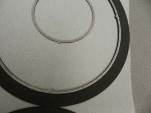
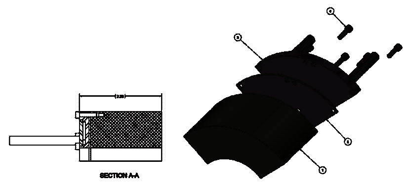
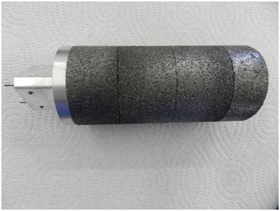
S-Bond Technologies’ active solder joining solutions have been used by by Fermi National Accelerator Laboratory for joining carbon:carbon and pyrolytic graphite in its particle accelerator program.  The improved Forward Particle Detector (FPIX) is to be used in Compact Muon Solenoid (CMS) and used for high-resolution, 3D tracking points, essential for pattern recognition and precise vertexing, all embedded in a hostile radiation environment.

The challenge posed by Fermi Lab to S-Bond Technologies, was to create high thermal conductivity metallic bonds between the ends of thermally pyrolytic graphite (TPG) blades and carbon:carbon composite end walls of a turbine nozzle like assembly. Figure 1(a-b) shows ¼ of a full assembly that was built using S-Bond joining and S-Bond 220 solder and processing. S-Bond’s active solder processing was successfully demonstrated and is in the technical roadmap for assembling Fermi Lab’s particle accelerator FPIX.  In this work, regular adhesives were not conductive and would off-gas in the extremely high vacuum environments, hence the selection of the active metal solder filler, S-Bond 220.

2013-03-25 058


Figures 2 – 4 show various assembly steps that all utilize the S-Bond carbon:carbon joining process described elsewhere in our technical blog. The process started with the S-Bond metallization on the TPG blades, Figure 2,  and the C:C nozzle endwall slots

2013-02-26 407
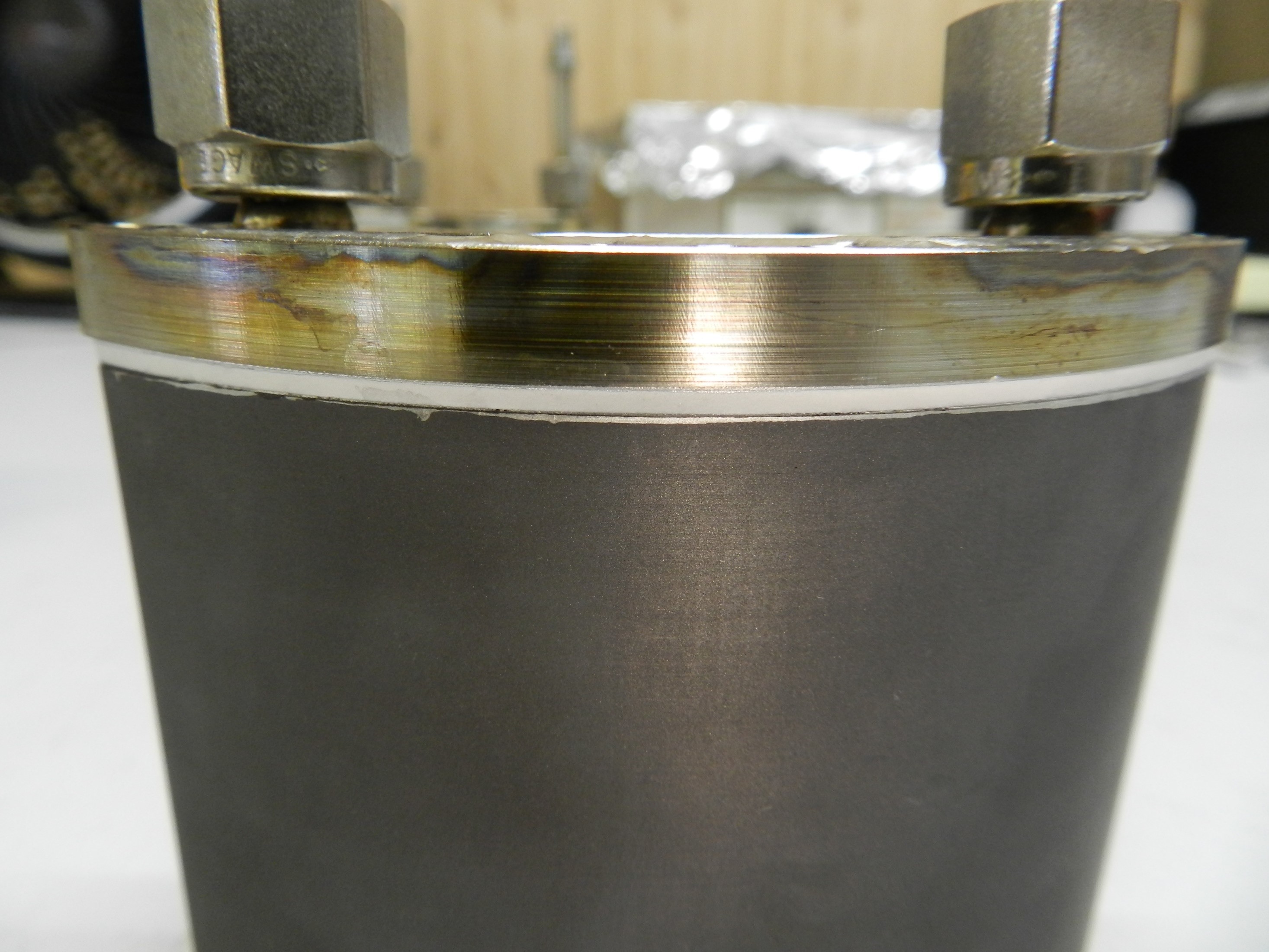
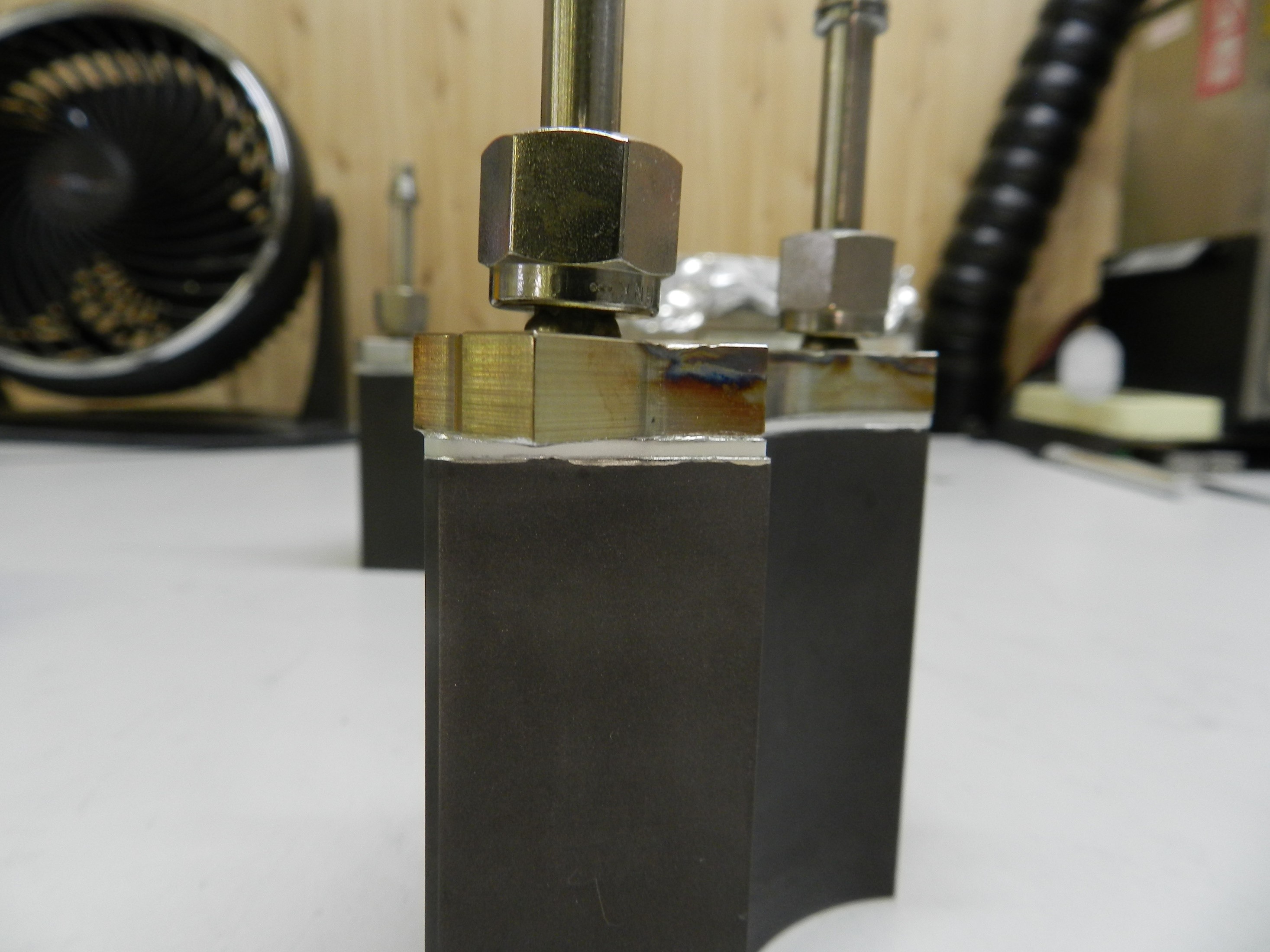
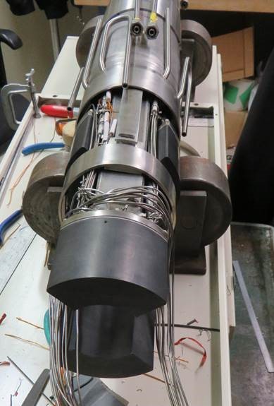
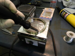
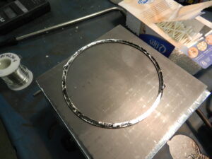
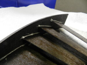
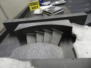
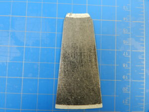
where the blades were inserted, Figure 3. After metallization, the blade and nozzle segments were inserted into a heated alignment press, Figure 4. After heating and insertion, the nozzle segment/ TPG blade assembly was cooled and removed. Figures 1a – b, above, showed the final fully bonded assembly.
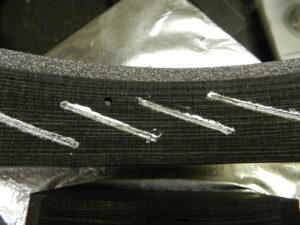


2013-03-25 007

Assy-FermiNozzle1


Please contact us if you have challenging graphite / carbon joining applications where S-Bond Technologies active solders can solve your joining problems.

Bonding Graphite Felts To Metals

Graphite and carbon felts are increasingly being used for applications in solar, LED, medical, semiconductor, automotive and energy storage systems.

S-Bond Technologies (SBT) has customized it S-Bond (S-B) processes to bond graphite felts to metals for such applications. In the process, graphite felts are first S-B metallized using a paste and vacuum process to create a metallurgical bond between graphite and the SBT active solder filler metals. After S-B metalizing of the graphite, only the tips of the felt surfaces are metallized and thus solderable to the opposing metal plates that are coated with SBT active solders.  The S-B metallization process does not fill the open cells of the graphite felts with S-B alloys, hence its advantage for bonding open cell structures.
(more…)

S-Bond Joined Phase Change Materials (PCM’s) Heat Sinks

S-Bond® active solders are being used extensively as a high conductivity bonding solution for foam cored phase change materials foam cored heat sinks. Increasingly, thermal management in electronics is the limiting factor in performance and/or life of electronics as higher power and higher speed in electronic devices generate more intense heat. High brightness LED’s, high speed/high bandwidth telecommunications, avionics, satellites and solid state conversion devices all have transient and steady power states where intense heat is generated and needs to be channeled away from the electronic device to prevent performance loss or permanent damage. The electronic industry is relying on a host of devices from conventional heat sinks with fins and fans to heat pipes and vapor chambers to more exotic materials and composites that include pyrolytic graphite or diamond. S-Bond materials and processes have been proven to be a good solution when bonding these various components and materials with a metallic “thermal interface material (TIM)” rather than filled polymeric bonding agents.

When electronics have a high transient heat output thermal engineers are using “phase change” heat sinks. Such heat sinks utilize “phase change materials (PCM’s)” that when exposed to heat absorb it very quickly and effectively as the material “changes phase”… either going from solid to liquid or liquid to vapor. Materials with high latent heats of fusion or latent heat of vaporization at or near the maximum temperatures that electronics are being used in the core of such heat sinks. In PCM heat sinks during the phase change there is the potential to rapidly absorb a high heat load… that can later be more slowly released to the atmosphere with cooling fins as the phase change is reversed and the heat is released away from the electronic device.

Two of the most used PCM’s are paraffin and water… each has a high latent heat of fusion or heat of vaporization, respectively. The challenge in the use of PCM’s is to overcome their relatively low thermal conductivities. For example, in heat sinks with paraffin as the PCM, when the heat transfers from the electronic device into the heat sink package, the outer layer of paraffin melts and then slows the transfer of heat into the solid paraffin core. To offset this heat flow limitation, designers are incorporating metallic or graphitic foams into the core of the heat sinks. The foams’ cells separate the PCM’s into small reservoirs that are surrounded by high thermal conductivity cell walls that then transfer the heat to a small PCM filled pore in the foam and therefore quickly melts the paraffin or vaporizes the water. Later in the “reverse” cycle, the conductive foam “cell walls” transfer the heat out of the PCM filled pores to solidify or condense the full volume PCM in the heat sink.

S-Bond joining has found excellent application in paraffin based PCM heat sinks in combination with graphitic foams (PocoFoam® or K-Foam®). S-Bond can effectively bond to graphite and graphite foams to heat sink package materials such as aluminum, copper and many heat sinks composites such Al-SiC, Al-Gr, Cu-W or Cu-Gr. In such graphite core/paraffin heat sinks. S-Bond Technologies has S-Bond metallized the Gr-Foam preparing for it to be soldered directly to the heat sink package. After S-Bond metallization, various S-Bond solders and processing can be used to bond the graphite foam to the components of the heat sink.

Heat Sink for Laser Diode Packages
Figure 1. Paraffin “PCM” / Graphite Foam cored heat sink for laser diode packages.

Figure 1 shows a PCM core finned Aluminum heat sink box used to cool high power laser diode packages mounted on the flat side opposite the side with the fins. The aluminum box contains a core of graphite foam bonded to the walls and base of the aluminum enclosure. The aluminum enclosure is then heated to 100˚C and filled and infiltrated with paraffin PCM’s. After filling the enclosure is sealed and the assembly is a PCM heat sink. When the laser diodes are on for intermittent periods of time the graphite foams thermally bonded to the wall of the enclosure heat the PCM… later when the heat load from the diodes are off, the bonded fins with air convection assist, cool and solidify the paraffin PCM to get the heat sink ready for the next thermal cycle. S-Bond active solder joining enabled the graphite foam to have an excellent thermal interface to the enclosure without filling the graphite foam and compromising the graphite foam’s ability to hold and transfer heat quickly to the paraffin PCM.

Heat Sink for Hot Fluid Channeled into Core
Figure 2. Graphite foam cored PCM heat sink for hot fluid channeled into the core.

Figure 2 shows another type of PCM cooling. The alternating bonded fluid circulating aluminum tubes bonded with S-Bond sandwiched between S-Bond metallized and bonded graphite foam plates. The stack is later encased in an enclosure and paraffin PCM is infiltrated into the foam to make a large ~ 24” x 24” x 12” PCM heat sink. When heated fluids circulate in the aluminum tubes the PCM filled graphite foam core rapidly absorbs the heat from the fluid.

Graphite foam wrapped heat pipe PCM heat sink
Figure 3. Graphite foam “wrapped” heat pipe PCM heat sink.

Figure 3 illustrates another style of PCM heat sinks that are mounted around a central heat pipe. In this design, S-Bond metallization of the faces and ID’s of the graphite annular rings permitted a graphite foam outer core to be become an effective PCM heat sink for a heat pipe cored thermal management device.

Contact us to evaluate how S-Bond can be used to enable your thermal management components to be made and how phase change material (PCM) heat sinks can be effectively incorporated into your designs.

Graphite / Carbon Joined to Metals with S-Bond®

S-Bond® active solders enable graphite bonding and the joining of other carbon or carbide based materials to each other and to most metals within the constraints of thermal expansion mismatch. S-Bond alloys have active elements such as titanium and cerium added to Sn-Ag, Sn-In-Ag, and Sn-Bi alloys to create a solder that can be reacted directly with the carbon surfaces prior to bonding using specialized S-Bond treatments prior to solder joining. Reliable joints have been made between graphite and carbon based materials with all metals including steel, stainless steels, titanium, nickel alloys, copper and aluminum alloys… (more…)

Joining Dissimilar Materials

The Issue of Coefficient of Thermal Expansion (CTE) Mismatch

Yes, S-Bond can join a wide variety of materials, including aluminum, copper, stainless steel, refractory metals and ceramic to metal brazing with aluminum oxide, aluminum nitride, silicon carbide and other oxide, nitrides and carbides… however, with this wide variety of materials joining capability, we have a lot of inquiries about aluminum soldering to stainless steel or aluminum oxide, graphite bonding to aluminum, titanium to silicon carbide, etc. (more…)